
Use Biomass Boilers Reduced carbon Footprint
The term “ biomass boilers ” refers to all boilers and systems powered by fuels of organic origin, i.e. waste, residues and industrial and urban waste of vegetal or animal origin that can no longer be reused, but which can be transformed into electrical energy and heat.
As defined by the European Directive 2009/28/EC, biomass is “ the biodegradable fraction of products, waste and residues of biological origin from agriculture (including vegetal and animal substances), forestry and related industries, including fishing and aquaculture, as well as the biodegradable fraction of industrial and municipal waste ”.
Biomass and the fuels derived from it represent a renewable energy source, since the carbon dioxide they emit during the combustion process is more or less the same as that which plants absorb during their life and release once they die. The combustion of biomass does not therefore lead to an increase in carbon dioxide in the atmosphere, the main cause of the greenhouse effect, but rather constitutes a further advantage for the environment given the biodegradability of the substances that are burned.
Our boilers are designed to burn both biomasses now considered commonly used, such as wet wood chips and pellets, and biomasses derived from organic waste such as sawdust, briquettes, bark, chicken manure, mushroom beds, miscanthus, nutshells, peat, CDR, vine shoots, pomace, grape marc.
For specific fuels we require a chemical analysis, on the basis of which we can then design a customized system.
The disposal of industrial processing waste has a significant impact on company costs. Biomass systems allow waste to be transformed into a resource, obtaining electrical energy and heat from its combustion.
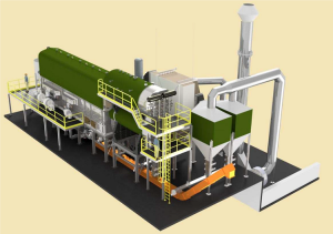
The biomass systems we design are suitable for any type of industrial process and comply with pollution regulations. The boilers can be built with “water jacket” technology, which allows for smaller dimensions and higher yields, but are also available with an adiabatic chamber. We supply complete systems, from the storage/feeding system, transport, combustion and fume filtering.
We follow and support our customers in every phase of the project, from the choice of the machine to the commissioning.
Usually the plant is divided into various sections of which the main ones are:
- Storage silo
- Power system
- Water heater
- Combustion grate
- Filtering
- Fireplace
-
Storage silo
The storage silo is the part of the plant where the biomass is stored, to then be moved and transported to the feeding system.
We can create different types of storage silos depending on the characteristics of the fuel and the customer’s needs.
-
Power system
From the storage silo the biomass is transported to the boiler and poured onto the combustion grate through the feeding system. The latter is generally made up of one or more augers or a chain conveyor (or both), designed to ensure the necessary supply of fuel to the boiler.
The system is designed in compliance with safety and fire prevention regulations.
-
Water heater
Biomass boilers consist of a combustion chamber and a heat exchanger.
The combustion chamber is equipped with fans for air supply and probes for combustion parameter control. The chamber can be adiabatic or wet chamber. Combustion, which can take place on a fixed or mobile grate, produces hot fumes that go into the heat exchanger, and ash as waste. The ash can be collected either with automated systems or manually.
The heat exchanger uses the energy of the fumes to produce hot water, superheated water, steam, etc., depending on the type of system selected. All safety accessories and the system for automatic exchanger cleaning are generally included in the supply.
Our boilers are built in compliance with the latest regulations and can be certified according to ASME, PED, etc.
-
Combustion grate
The grill or brazier is the area where the material for combustion is poured. There are 3 types of grills:
- Fixed flat
- Flat furniture
- Inclined mobile
The flat fixed grate is the simplest; it is an economical system that requires regular manual cleaning of the ash.
The mobile grates are used for medium-large sized systems and are equipped with systems for automatic ash expulsion. This type of grate allows control over the progress of combustion, thus ensuring greater efficiency.
-
Filtering
The fumes at the exchanger outlet must be “cleaned” and, generally, two systems are used for this purpose (separately or together):
-
Cyclone (or multi-cyclone) filters for initial filtering that complies with the main pollution regulations;
-
Bag or electrostatic filters for superior filtration
-
Fireplace
After filtering, the fumes are pushed by the tail fan through the chimney and expelled into the atmosphere.
Other components may be present in a biomass plant depending on the characteristics of the fuel and the customer’s requests; correct initial design is essential to prevent possible future inconveniences.
BIOMASS PLANTS
The use of biomass has ancient origins, wood has always been burned for heating and cooking. Today, individual consumption has developed on a large scale, adapting to the most varied industrial applications.
Modern power plants are able to exploit the energy contained in biomass to produce hot water, superheated water, steam and electricity, reducing the environmental impact to a minimum compared to non-renewable energy sources.
Hot water
For water temperatures below 110/115°C, hot water boilers are used. The most common uses are in the central heating sector of hospitals, greenhouses, industrial warehouses, etc. Thanks to the simplicity of the system and the undemanding management, hot water systems are preferred to others within the limits described above.
Superheated water
For water temperatures above 110/115°C, superheated water boilers are used. The most common uses are in the district heating sector and specific industrial applications (food, manufacturing, etc.). This type of system is also used in cogeneration plants.
Steam
Our range of biomass boilers includes biomass steam generators (saturated or superheated). Applications range from industrial (food, pharmaceutical, etc.) to electricity generation with steam turbines.
Cogeneration and trigeneration
The term “cogeneration plants” refers to those systems that allow the combined production of electricity and heat. When we talk about trigeneration, we are referring to systems that can produce three distinct forms of energy: electricity, heat and cooling.
We can provide turnkey cogeneration and trigeneration plants.
Boilers
| Model | Typology | Minimum potential | Maximum potential |
| GPT – AC | Smoke pipes, 3 turns, hot water production | 900 kW | 9000 kW |
| GPT – AS | Smoke pipes, 3 turns, superheated water production | 900 kW | 9000 kW |
| GPT – CP | Smoke pipes, 3 turns, steam production | 1000 kg/h | 12000 kg/h |
| GPT – HA | Smoke pipes, 3 turns, hot air production | 400 kW | 1500 kW |
| GPT – PW | Cogeneration | 50 kWe | 5000 kWe |
| Standard boiler data | Design pressure | Boiler room dimensions (mm) | Potential | Maximum weight with water (kg) |
||||
| GrillGF-P | GrillGF-M30 | GrillGM-M30 | Grill
GM-M50 |
|||||
| 1200 | GPT/AC | 6 bars 10 bars |
8000×5000 H.4200 | 9000×6000 H.4500 | 9000×6000 H.4500 | 9000×6000 H.5000 | 1200 kW | 18,800 |
| GPT/AS | 8000×5000 H.4350 | 9000×6000 H.4650 | 9000×6000 H.4650 | 9000×6000 H.5150 | 1200 kW | 18,800 | ||
| GPT/CP | 8500×6000 H.5880 | 8500×6000 H.5880 | 9000X6500 H.5960 | 9000X6500 H.6520 | 1860 kg/h | 23,800 | ||
| 1650 | GPT/AC | 6 bars 10 bars |
8500×6000 H.4200 | 8500×6000 H.4500 | 9500×7700 H.4500 | 9500×7700 H.4800 | 1650 kW | 26.100 |
| GPT/AS | 8500×6000 H.4350 | 8500×6000 H.4650 | 9500×7700 H.4650 | 9500×7700 H.4950 | 1650 kW | 26.100 | ||
| GPT/CP | 9500×7000 H.6420 | 9500×7000 H.6420 | 9500×8000 H.6500 | 9500×8000 H.7100 | 2560 kg/h | 30.800 | ||
| 2100 | GPT/AC | 6 bars 10 bars |
10000×7500 H.4600 | 10000×7500 H.4900 | 9500×8500 H.6000 | 9500×8500 H.5700 | 2100 kW | 35.800 |
| GPT/AS | 10000×7500 H.4750 | 10000×7500 H.5050 | 9500×8500 H.6150 | 9500×8500 H.5850 | 2100 kW | 35.800 | ||
| GPT/CP | 9500×8000 H.7145 | 9500×8000 H.7145 | 9500×9000 H.8270 | 9500×9000 H.8270 | 3255 kg/h | 43.300 | ||
| 3000 | GPT/AC | 6 bars 10 bars |
11000×8500 H.5500 | 11000×8500 H.5800 | 11000×8500 H.5800 | 10500×8500 H.6947 | 3000 kW | 50.800 |
| GPT/AS | 11000×8500 H.5650 | 11000×8500 H.5950 | 11000×8500 H.5950 | 10500×8500 H.7097 | 3000 kW | 50.800 | ||
| GPT/CP | 11000×9000 H.8200 | 10500×9000 H.9450 | 10500×9000 H.9530 | 10500×9000 H.9450 | 4650 kg/h | 60,000 | ||
| The following special models are also available: |
| • 7000 with potential 7000 kW 10850 kg/h |
| • 9000 with potential 9000 kW 12000 kg/h |
Standard design pressures from 6 bar to 25 bar – Higher design pressures available on request. .
For any requests for special models and applications and/or different from those in the catalogue, a feasibility analysis must be carried out.
Grids
| Model | Typology | Minimum potential | Maximum potential |
| GF – P | Fixed pellet grill | 900 kW | 3000 kW |
| GF-M30 | Fixed grid for wood chips maximum humidity 30% | 900 kW | 3000 kW |
| GM – M30 | Mobile grate for wood chips maximum humidity 30% | 900 kW | 9000 kW |
| GM – M50 | Mobile grate for wood chips maximum humidity 50% | 900 kW | 9000 kW |


Monica Brandson
Eu ut id pariatur laboris culpa. Aliqua esse magna labore mollit eu magna aliquip labore. Cillum occaecat esse duis laboris deserunt enim occaecat magna.